This article explains how to plan a mission and collect data with the Wingtra LIDAR payload. It provides best practices and limitations of the system. It consists of the following sections:
- Create a flight plan - flight parameters
- System limitations
- Set up the base station
- Accuracy assessment
- Sensor calibration
- Pre-flight checklist
- Post-flight
Create a flight plan - flight parameters
Create a new flight plan and select LIDAR from the payloads list. Create the flight plan, set the take-off and landing location, and create an area or corridor as described in the article: Create a new flight plan. The flight parameters for flying with LIDAR are discussed below.
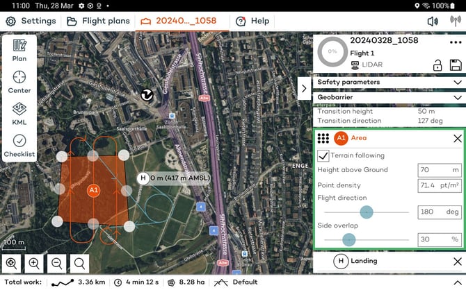
Terrain following: You can define whether terrain following should be enabled for each area. The Terrain following article explains this feature in detail.
The Wingtra LIDAR sensor typically flies lower than RGB cameras to achieve similar accuracy, so precautions should be taken to ensure the area is clear of obstacles. Terrain following should be enabled, and since the Wingtra One GEN II flies at a fixed height above the highest point on a flight line, it is important to fly perpendicular to the slope to capture a consistent point density. For more details on planning such a mission, refer to this advanced flight planning Knowledge Base article.
Flight height: Setting the height above ground is a key parameter to consider during mission planning because of the laser range and point density. The maximum range of the scanner is 300m, but as you fly higher the chance of detecting a point on a surface with low reflectivity decreases. The FoV also shortens because on the edges the laser pulse needs to travel further. The higher the altitude the more points are missed on the sides which reduces the effective FoV so when flying higher overlap should be increased to compensate.
| Altitude (m) | Probability of detection (POD) | Half FoV (deg) |
| 45 | 100% | 45 |
| 60 | 100% | 43 |
| 90 | 96% | 41 |
| 120 | 86% | 34 |
| 150 | 76% | 31 |
In this table, the probability of detection (POD) is a function of ambient light, distance from the target, the surface's reflectivity, and the beam's angle to the surface. Assuming that factors other than height remain constant the chart shows that POD decreases as the height from the surface increases.
The ideal range for high accuracy and detection is between 60 and 90m. For thin structures like power lines, it is suggested to fly 30-50m above the structure parallel to the lines. When mapping vegetation, the accuracy decreases due to lower ground point density. The flight height should be set so that it fits the mission objectives of accuracy and point density.
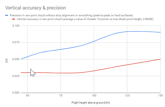
In the chart above the blue line represents the precision of the point cloud thickness also known as noise. The red line indicates the expected accuracy compared to a checkpoint. Keep this chart in mind when setting the flight height to meet the mission targets.
Point density: This is an average calculation of the density of point features around each output raster cell. Wingtra defines the average point density at 45m AGL (single pass, single return) to be 110pt/m^2. The estimated point density is inversely proportional to the flight height - the higher the flight, the lower the point density.
Point density is calculated based on several factors:
- LIDAR Scanner Field of View - the active horizontal radial FoV is 90deg out of 360deg and the vertical FoV is 40.3deg
- Flight Height - set by the user
- Flight Speed - fixed at 16m/s
- LIDAR Scan Rate - 480’000 pts/s for 3 returns
- Overlap of Flight Lines - defined by the user, but default to 50%
In WingtraPilot the point density estimate is based on a single pass so sidelap is not taken into consideration. If the sidelap parameter is changed the point density value in the application will not change but will in real life.
Since the flight speed, FoV, and LIDAR scan rate are fixed, only the flight height and overlap parameters in WingtraPilot can impact the point density.
Wind and surface type are also variable factors in point density which is why the values are average estimates.
Flight direction: This defines the flight direction and in regards to LIDAR it is important to consider point density factors with terrain and wind. The drone should maintain a consistent height above ground and fly perpendicular to the wind.
To keep density consistent fly perpendicular to the wind to avoid high tailwinds because higher speeds reduce density. For how to plan the flight in windy conditions, check here.
Terrain following should be prioritized over wind so if it is not possible to modify the wind direction then under parallel direction increase to 50% sidelap to maintain consistent density as long as the flight has an upwind and downwind strip adjacent to each other.
Side overlap: This defines the percentage of overlap between adjacent flight lines. The default overlap for LIDAR is 30%, which is suggested to maximize efficiency and quality. This is different from photogrammetry which defaults to 70% and also has a front overlap parameter.
The scope of the mission and the environment should be taken into account when setting the side overlap. For dense vegetation areas and areas with powerlines and thin structures, it is recommended that the overlap is increased to 55-60% to ensure double coverage of each flight strip.
To capture facade details on vertical structures, a crosshatch pattern is recommended as the horizontal FoV is radial which means it's wider, and the angle to the side will get more details on vertical structures. To create a crosshatch pattern, create two areas one on top of the other with perpendicular flight directions.
System limitations
Flight time and maximum altitude AMSL
Since the LIDAR sensor is heavier than other Wingtra payloads the flight time is reduced to 35 minutes when the Ultracharge+ is used, and slightly below 35 minutes when the standard charger is used. This time has been calculated with the parameters set below 500m AMSL and a transition height of 25m. To maximize flight time, keep the transition height as low as possible.
Because of the additional weight, the current altitude limit ceiling is 1500m AMSL with normal propellers and 2500m with high-altitude propellers. If the maximum height exceeds these values, a warning will appear in WingtraPilot.
For specific details about flying about 1500m with LIDAR please review the article best practices for flying in high altitudes
Flight line length
An important factor when planning flight lines is to ensure that the straight line length of a single line does not exceed more than 4.8km. This is because errors are introduced between the IMU and GNSS, which drift after a certain amount of time. Since fixed wings fly faster than multirotor drones, they are affected less, which is why the flight line length is higher than that of other drones.
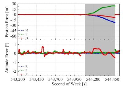
To fly a long straight corridor, it is suggested to break up the mission into smaller chunks, with loiter waypoints in between, to mitigate the potential for drift.
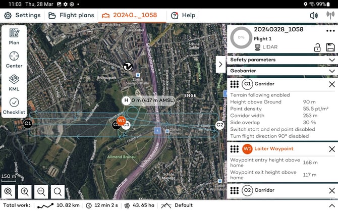
The most straightforward way to determine the flight line length is to import a polyline KML file and convert it into a corridor area. Alternatively, use the scale bar at the bottom left of WingtraPilot. The corridor length can also be calculated by dividing the total flight path length displayed in the Total Work section by the number of flight lines. For example, a 13.5km corridor with 3 lines means the individual lines are about 4.5km, with a waypoint circle in between.
Object Surface Reflectivity
Different object surfaces have varying rates of reflectivity. When factoring in point density, knowing how the surface reflects the laser pulse is important. Most object surfaces have a reflectivity of 10%.
Water is a strong absorber, and a typical LIDAR laser with a wavelength of 905nm will be absorbed directly. Unless the LIDAR is of the bathymetric type and the laser wavelength is shorter, it will not penetrate water.
Here are some examples of average surface reflectivity rates at 905 nm:
- Fresh asphalt: 4-7%
- Dry grass: 15-20%
- Forest canopy: 5-20%
- Wet concrete: 30-50%
- Snow: 60-90%
Given the same material, white objects have a higher reflectivity than black objects, smooth objects have higher reflectivity than rough objects, and objects with higher reflectivity are easier to perceive.
Black can absorb the laser pulse, and moisture on dark pavement surfaces can cause issues. Flying lower helps with the intensity of the return to pick-up. If flying lower is not possible, wait for dryer conditions. The more points missed, the lower the point density, so if the environmental conditions are not favorable, increase overlap and fly lower.
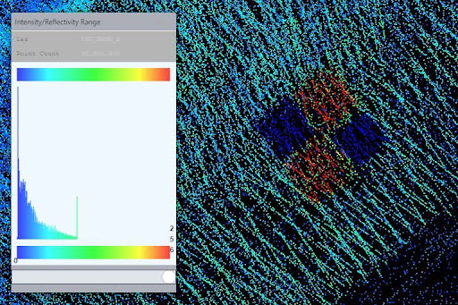
Intensity is a relative measure of the return strength of the laser pulse that generated the point. It is based largely on the surface reflectivity of the object being measured as well as atmospheric conditions, laser beam divergence, and angle of incidence of the laser. Intensity aids in feature detection and extraction in LIDAR classification, but a user should be aware that humidity in the air column, as well as a change in reflectance of the measured object (such as being wet, or viewed from a different angle of incidence), will result in differing intensity values between successive lidar collections of the same scene.
Set up the base station
Wingtra utilizes a PPK-only workflow for LIDAR and requires GNSS files captured from a base station. PPK corrections are a key step in the LIDAR process as higher accuracy is required compared to photogrammetric processing, as LIDAR is a direct measurement.
Please follow our Base Station Best Practices article. Enable all available constellations (GPS, GLONASS, Beidou, Galileo) and note precisely the pole height and ARP-APC offset. With LIDAR, it is important to use a high-quality base station with optimized settings and a 1-second internal logging.
The base station and the PPK module on the drone (rover) receive and log GNSS observations. These observations (combined with precise IMU data on the LIDAR) can be merged in the PPK processing step to create a highly accurate trajectory.
The recommended base station setup for LIDAR is to set up a local receiver over a point with known coordinates.
The mismeasured height of the antenna above the mark is probably the most pervasive and frequent blunder in GPS control surveying.
For survey-grade absolute accuracy, use a base station from a reliable manufacturer that is as close as possible to the mapping area, preferably within it.
Start logging at least 5 minutes before take-off and, stop 5 minutes after landing. To include all GNSS constellations and all visible satellites, export to a RINEX version > 3.0. Version 2.11 can work to process data, but it is not suggested because it only includes GPS+GLONASS.
After the export from the base station is completed, ensure that all RINEX files are transferred to the laptop, not just the observation (.o) file. It is highly recommended not to change the naming of the RINEX files or make other modifications. It is recommended to export a report of the base station location and ensure that the coordinates are in a geodetic datum format.
Accuracy assessment
Checkpoints are required to perform an accuracy assessment of the point cloud. The checkpoints are unbiased ground measurements within the mapping area. The assessment can happen in third-party software, but they should be captured in the dataset.
To avoid errors and offsets because the checkpoints are off, make sure to define the coordinates according to surveying standards - it is recommended to use RTK rovers connected to the same base the RINEX came from. The alternative is to connect the RTK rover to a local CORS/VRS network to establish the checkpoints but ensure that the same station is used to process the LIDAR data
The vertical accuracy check is straightforward and automatic. The software compares the checkpoint height to the average of the LIDAR points surrounding it.
On the other hand, horizontal accuracy checks can be more challenging due to lidar point density and lack of surface-to-point comparison. The best option is to use special reflective targets that are visible in a point cloud. Ideally, the target should be a large checkerboard or chevron pattern with highly contrasting colors like black/white. Place the targets on a flat surface and avoid elevated objects like building corners and hydrants.
If such markers are lacking, traffic horizontal signalization, e.g., parking lot stripes, tends to stick out well in intensity maps due to retro-reflective thermoplastic materials.
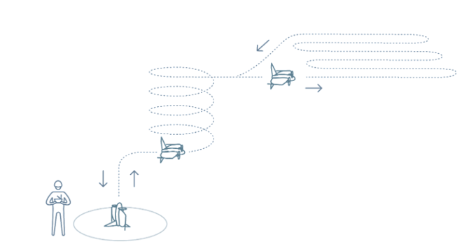
Calibration
Most LIDAR payloads in the market require a calibration before flying the mission. For example, a figure 8 pattern needs to be flown before the mission, and in case of a long line a pattern to calibrate in-flight. The Wingtra LIDAR does not need extra calibration procedures as it happens automatically during the take-off, transition, and climb to the mission. The flight pattern in the turns also acts as a calibration loop between strips helping the data maintain a smooth alignment and consistency.
Pre-flight checklist
The pre-flight checklist is explained here. For the most part, it is the same workflow as other payloads besides assembling the antenna placing the top cover on the drone, and pressing the power button on the LIDAR payload to turn it on. The checklist differences compared to other payloads are in:
step 8 - the mapping sensor will go through a bootup sequence and health check to ensure everything is set up correctly.
step 14 - a command will start logging data on the scanner. The system will ensure that enough GNSS signals are available, enough USB space is available on the drive, and a delay of 30 seconds is enacted for INS calibration.
Ensure that the laser is clear before flight. Clean with a microfiber cloth or glass cleaner. Watch out for fingerprints, smudges, or dirt on the sensor.
Once all steps are green, proceed to take off.
After flight
After the flight, a message indicates the success of data collection and organization, like with all other payloads. The system will check to ensure that all the data is saved. Then, the batteries can be disconnected to turn off the drone and the payload.
To check the data sanity, remove the USB drive from the payload and insert it into a computer. The folder's name should match the flight plan. The files in the project folder should look like below:
 Open the data folder to verify that it contains files.
 After the flight, also ensure that the base station was logging data during the entire flight.