Setup new project
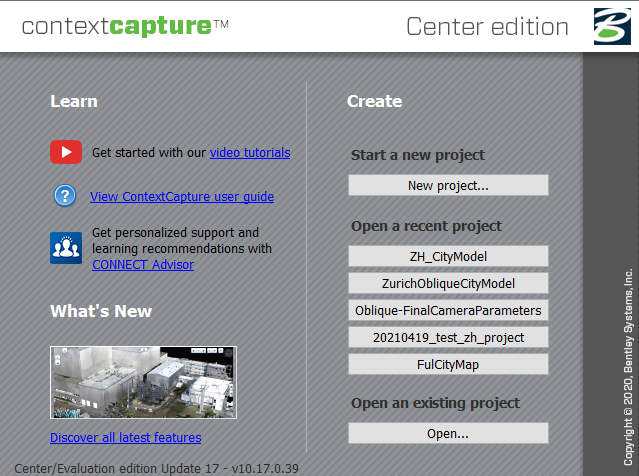
- Start a new project or open an existing one.
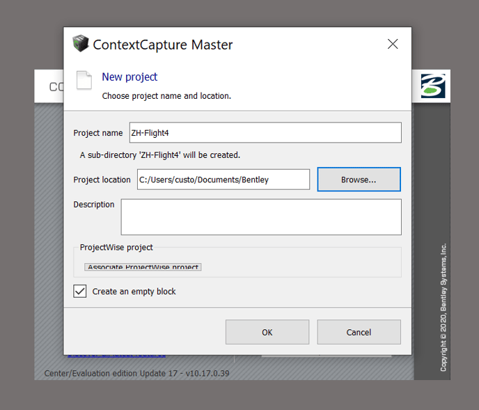
- Enter a project name and specify the path.
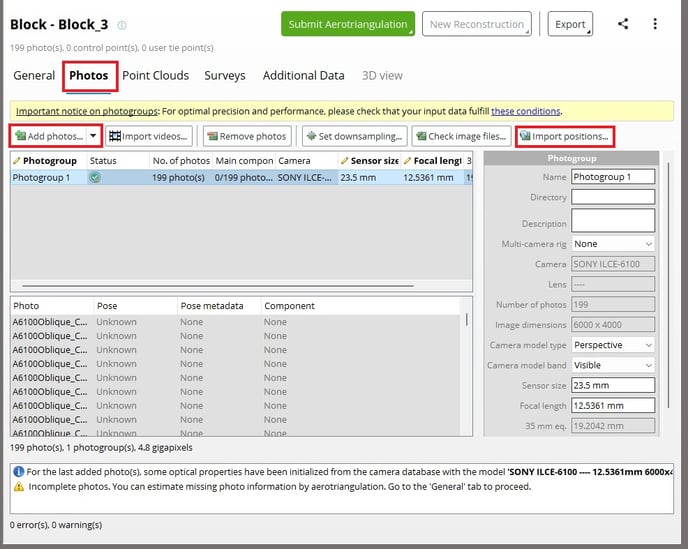
- Go to the Photos tab.
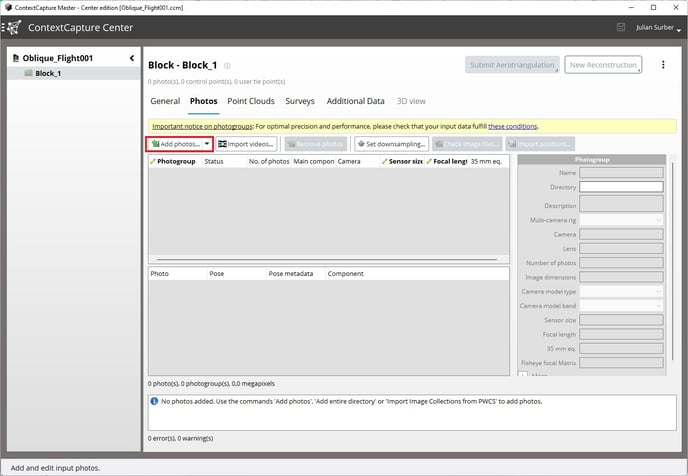
- Add images by selecting photos or by adding an entire directory. To import you have the following two options:
- Select the images in the OUTPUT folder. The coordinate system is automatically set to WGS84, ensure to specify the height system (PPK: Ellipsoidal height, Non-PPK: Sea level)
- Select the IMAGES folder and click on "Import Positions" to load the geotags from the .csv in the OUTPUT folder. You will be asked to specify the coordinate system of the geotags.
Importing Geotagged csv/txt data(Optional)
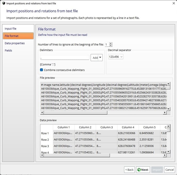
- To import geotagged points after importing your images, click on the Import Positions on the photos tag.
- After browsing to the location of your CSV file, specify “,” as the column delimiter.
- Next, select the Spatial reference system depending on the coordinate system of the geotags. Set the camera orientation to X right, Y up. Click next when you are done.
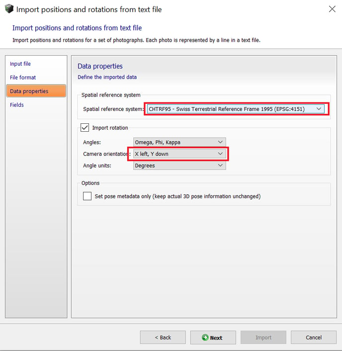
If aerotriangulation fails, disable Import rotation and try again.
Optional Importing Local/Geoidal vertical datums
- Please refer to this article
- The final step is to assign the column to match the column in your dataset. The default settings in WingtraHub are as follows:
Latitude -> Longitude -> Height -> Omega -> Phi -> Kappa
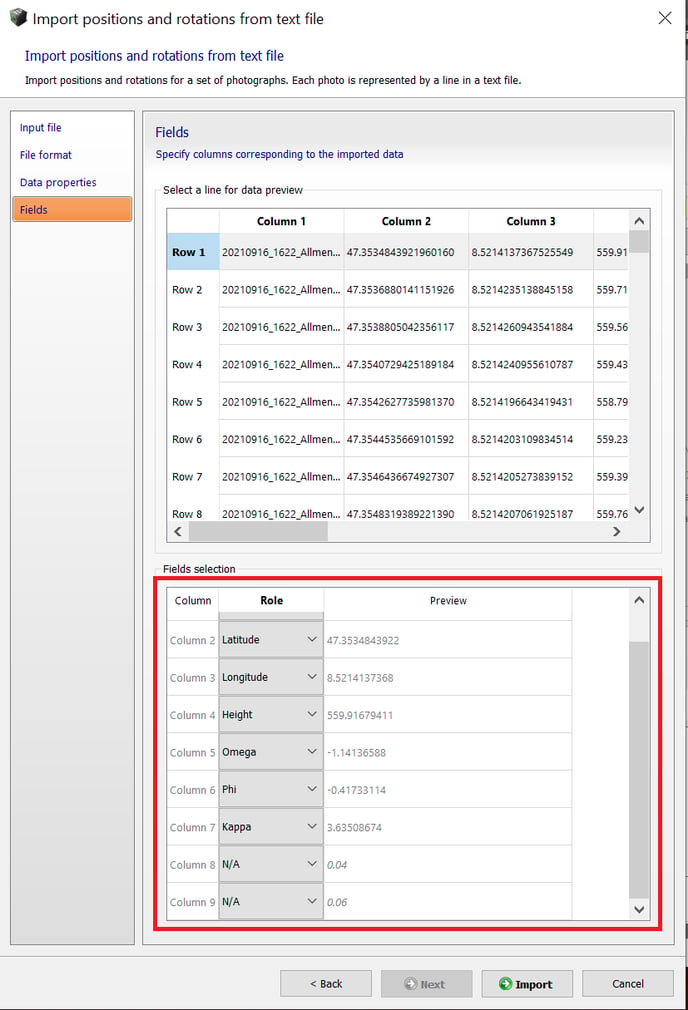
- Click on Import to complete the process.
When importing the geotags from CSV, you will need to manually specify the focal length: 12mm.
Include GCPs / checkpoints (optional)
By importing ground points, you can assess the accuracy of your project within Bentley ContextCapture. For more information on how many GCPs vs Checkpoints you should use, read the following article.
After setting up the project go to the "Surveys" tab and import a text file.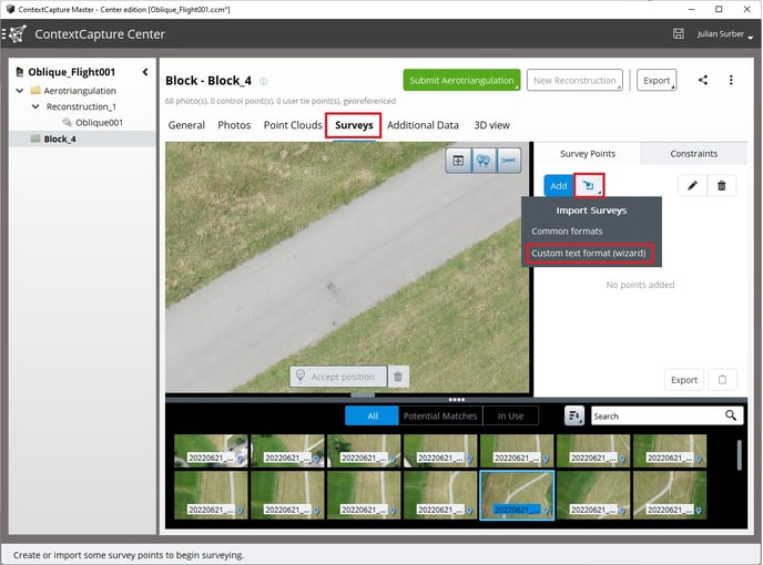
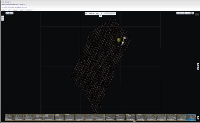
In the "3D view" tab, you can see the location of the checkpoints and the imported geotags. By clicking on one of the geotags close to a checkpoint, the respective image is highlighted in the preview list at the bottom. When changing back to the "Surveys" tab, the highlighted image that should contain a checkpoint will be displayed.
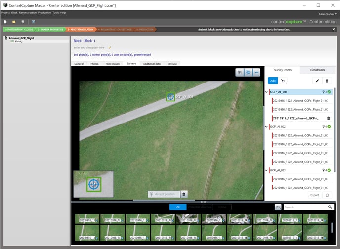
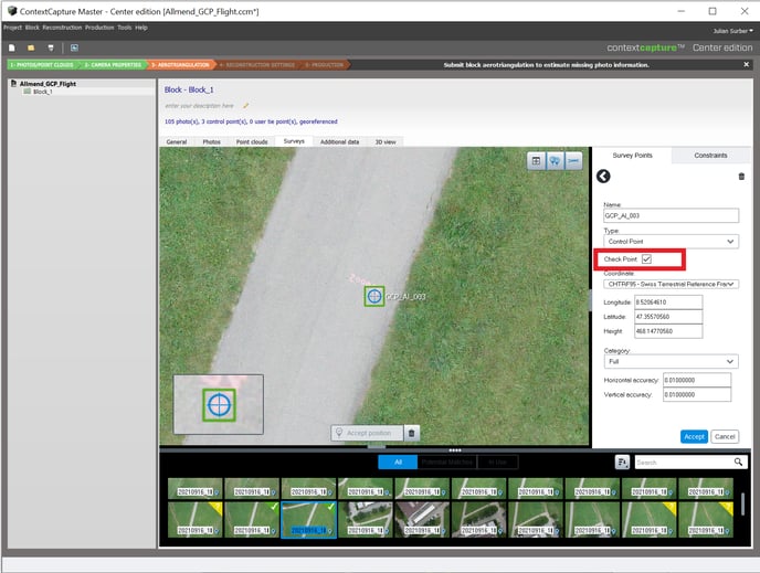
Zoom in on the checkpoint and right-click on the measured location and assign this location to one of the imported points.
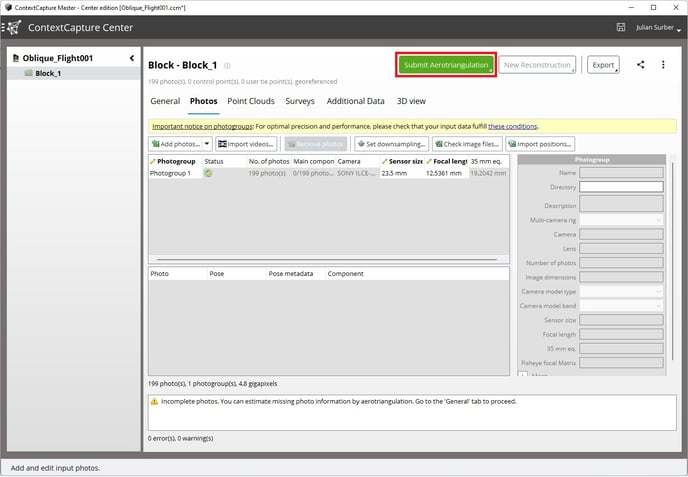
Run aerotriangulation
- Go to the General tab and click on "Submit aerotriangulation". Specify if you want to process the project on your desktop using ContextCapture Engine or in the cloud.
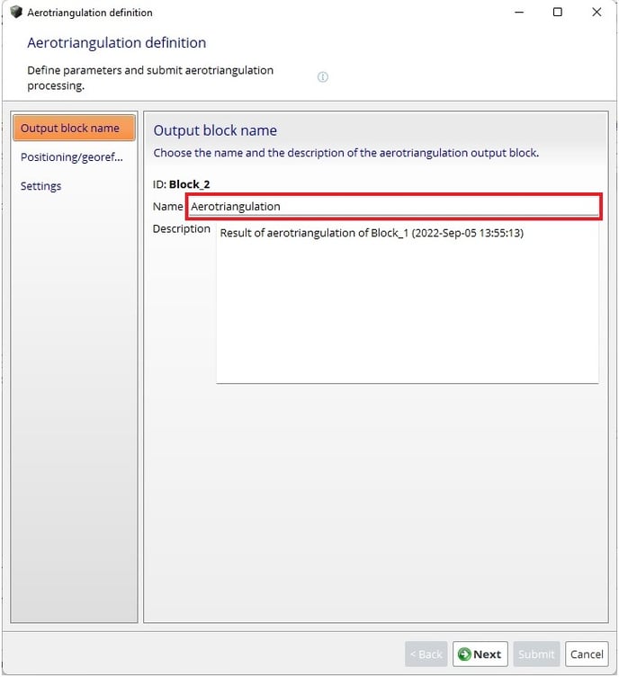
- Give the AT a name or use the default one.
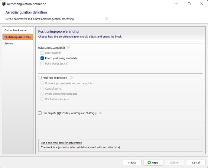
- Define the positioning settings. We recommend the following settings:
- For PPK flights, set the 'Adjustment constraints' to Photo positioning metadata and leave the 'Final rigid registration' unchecked.
- For non-PPK flights, leave the 'Adjustment constraints' unchecked and set the 'Final rigid registration' to 'control points'
- It is recommended to leave the Aerotriangulation settings at default :
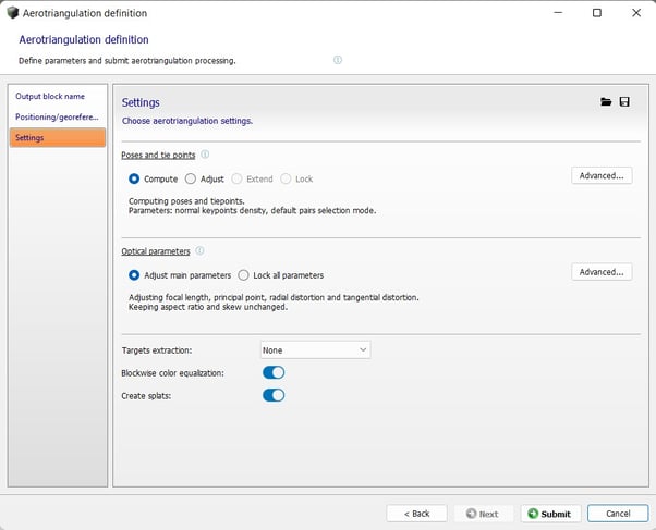
- Open ContextCapture Engine to start the aerotriangulation, if it is not open already.
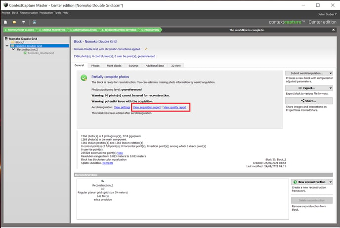
When the AT is finished, you can inspect the acquisition report and the quality report.
Generate 3D model
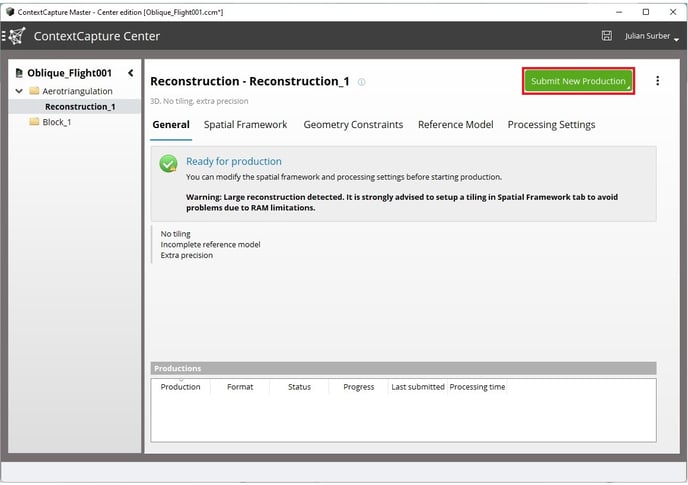
- In a fully processed AT block, you can start a new reconstruction on the bottom right to generate your map or 3D model.
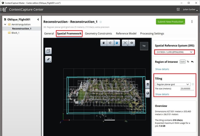
- In the newly created Reconstruction, there is a Spatial framework tab, where you can set the Spatial reference system, the processing bounding box, and the tiling.
It is highly recomended to use tiling to reduce the RAM used for processing. The processing will fail if there is not enough RAM available.
There are three tiling modes:
- Regular planar grid - Divides reconstruction into square tiles along the XY plane.
- Regular volumetric grid - Divides reconstruction into cubic tiles.
- Adaptive tiling - Adaptively subdivide reconstruction into boxes to meet the target RAM usage.
From the first two tiling modes, you can specify the tile size and see the estimated RAM usage for the job. With Adaptive tiling, you specify how much RAM to be used.
In the General tab, click on "Submit new Reconstruction" to start the reconstruction. If you get the warning: the expected maximum RAM usage exceeds 16GB*. It is strongly advisable to use a tiling.
*depending on the RAM capacity of your processing computer
- Purpose - Select the purpose of production. e.g 3D mesh, 3D point clouds, etc. This example is to produce a 3D mesh
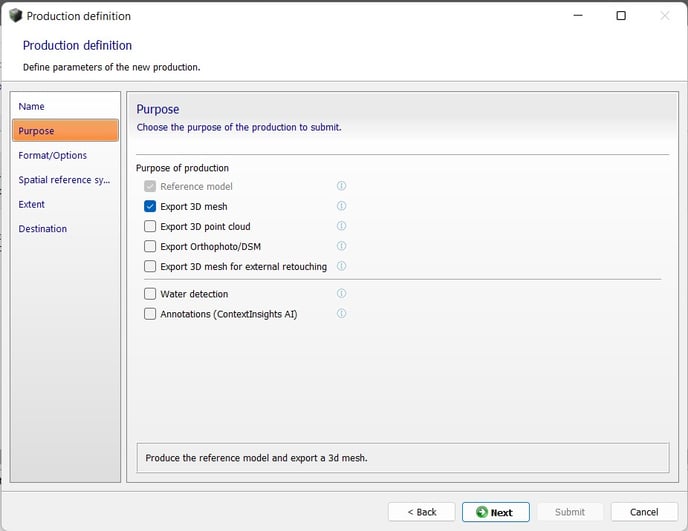
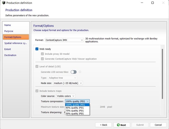
- There are different output formats for 3D mesh production. Select your preference with the Format drop-down list.
To produce a web sharable link select Contextcapture 3MX and make sure the Web ready button is checked.
- Set the texture compression to 100% quality JPEG for the best quality
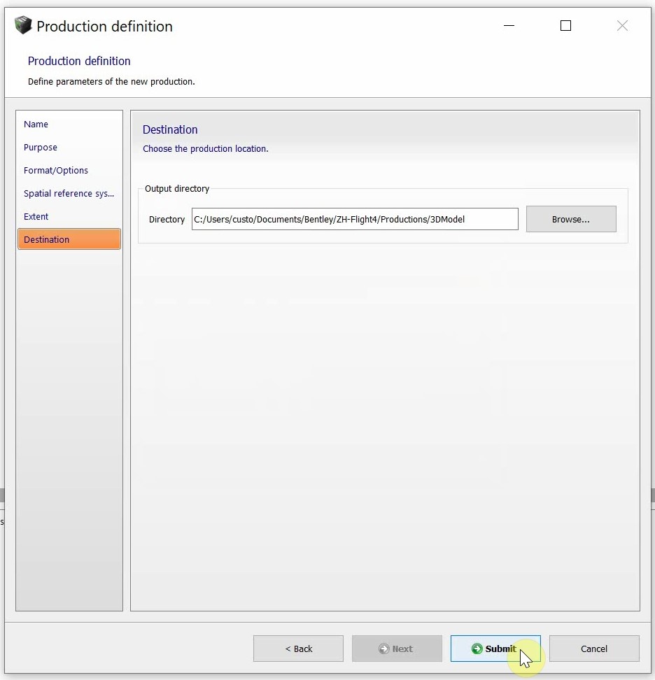
- Next, select the output spatial reference system and the extent of production.
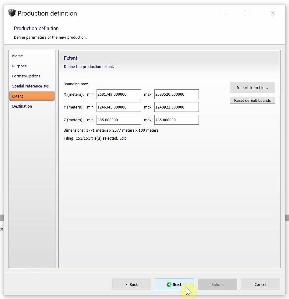
- Finally, select the output directory and click Submit to start production.