Before installing PIX4Dmatic read the minimum and recommended hardware requirements and ensure that your device fulfils the requirements.
PIX4Dmatic is faster and more reliable than PIX4Dmapper for corridors and large datasets of more than 5000 images.
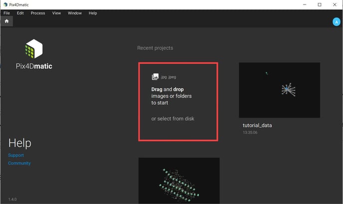
Step 1. Create the project in PIX4Dmatic
Open PIX4Dmatic and drag and drop the images or select the folder from the disk in the highlighted area.
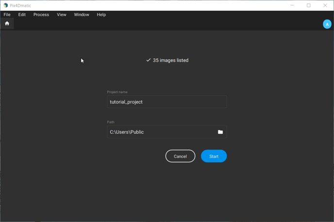
Specify the project name and the disk location where the project will be saved and click on Start.
Step 2. Image and output coordinate system
If the images imported contain geolocations and orientation information, it is automatically recognized by PIX4Dmatic.
Else, import the geolocation and orientations from File -> Import image geolocations and orientations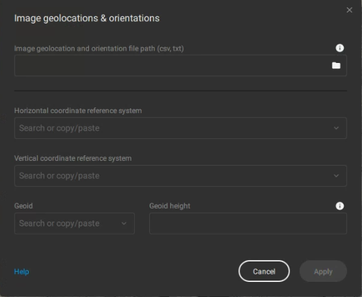
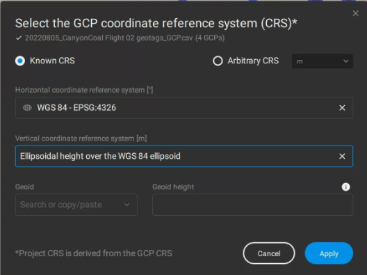
Browse and select the geolocation file and specify both the horizontal and vertical coordinate systems. For example, for PPK geotagged WingtraOne images where the base location in WingtraHub was provided in WGS 84 system, the horizontal image coordinate system in PIX4Dmatic is automatically set to WGS84 - EPSG:4326 and the vertical coordinate system is automatically set to ellipsoidal height over the WGS84 ellipsoid.
The coordinate system of the outputs is defined based on the location of the project. If the image coordinate system is WGS 84, the corresponding UTM zone is used as the output coordinate system.
The output coordinate system can be seen at the bottom of the window.
Step 3. (Optional) Import GCPs
When GCPs are used, the output coordinate system corresponds to the GCPs coordinate systems.
If the GCPs coordinate system is geodetic the corresponding UTM zone is used for the output coordinate system.
You can import your GCPs from File -> Import GCP's
Import a .txt or .csv with the GCPs coordinates following the format specifications of the PIX4D article and specify the coordinate system, horizontal and vertical, to which the GCPs refer.
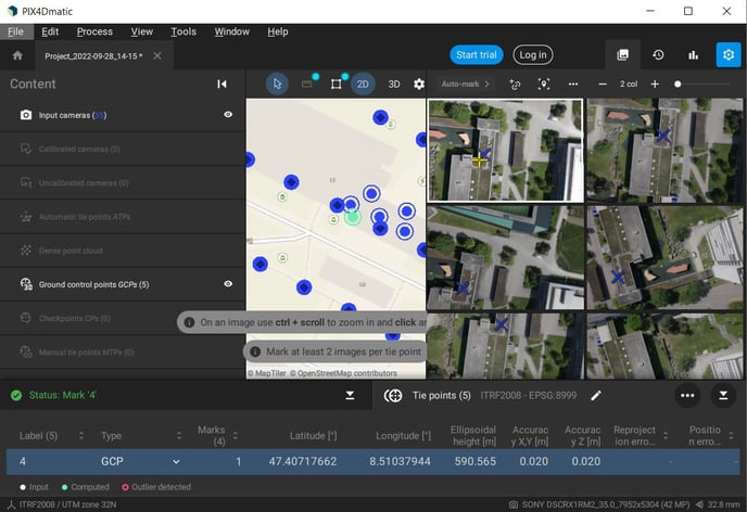
After the GCPs coordinates have been entered, you need to mark the GCPs.
Click on the GCP you want to mark and you will see the images where this is visible. The approximate position of the GCP appears with a blue X. Mark precisely the GCP on the image by zooming in and clicking on the target. The clicked position appears with a yellow cross.
Step 4. Image calibration
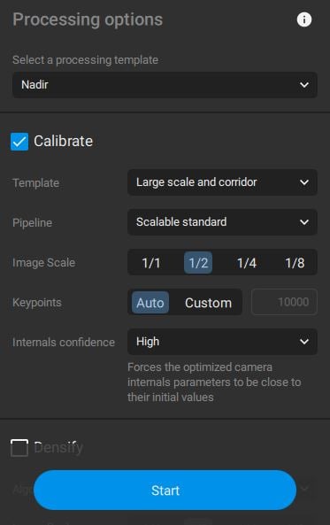
After creating the project and importing and marking the GCPs (optionally), the calibration of the images can start. Select Calibrate in the Process many and set the processing options for your project. For more details on the different processing options check this PIX4D article. Note that RX1 images are of high resolution. To speed up processing select the 1/2 option for the image scale. Then click on Start to start with the calibration process.
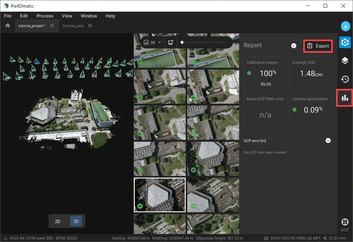
Step 5. Assess the calibration results
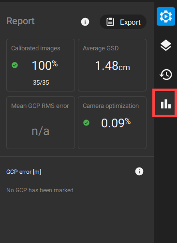
Once the images' calibration is finished, take a look at the report in PIX4Dmatic and see the number of calibrated images and the average GSD of the project. In case GCPs are used, check the mean GCP RMS error to assess the accuracy of your project.
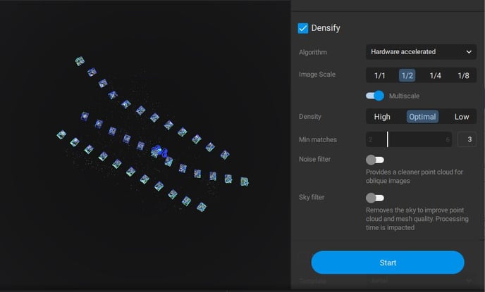
Step 6. Generate all the outputs for the project
Generate the point cloud, 3D mesh, DSM and orthomosaic of the mapping area. Select the options Densify, Mesh, DSM and Orthomosaic and click on Start. You can find the details about the processing options for each one of the outputs in the Pix4D knowledge base.
Once the processing is finished, you can export the report in a .pdf file format.