Flights are organized under sites. To learn how to create sites and flights, visit the article Sites and flights - WingtraCLOUD.
Features overview
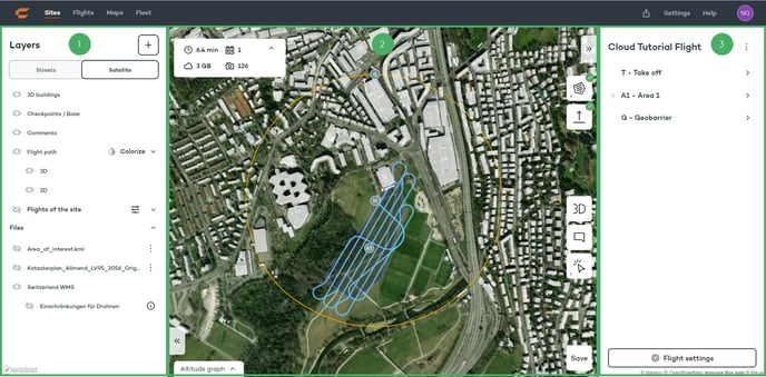
1) Layers tab:
- Add files (kml, dxf, geojson)
- Change between street and satellite view
- Show/hide 3D buildings
- Show/hide checkpoints & base station
- Show/hide comments
- Show/hide flight path (2D/3D)
- Colorize flight path (GSD, AGL, VLOS)
- Show/hide other flights of the site
- Show/hide files that have been added to the flight
2) Map view:
- Flight time, required battery pairs, storage space and number of images
- Show/hide altitude graph
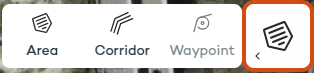
- Create an area, corridor or waypoint
- Define the home point
- Change between 2D and 3D view
- Add a comment
- Inspect terrain and layer metadata
- Safe the flight plan
3) Flight parameters tab:
- Share or lock the flight plan
- Adjust the take off parameters
- Adjust the area, corridor and waypoint parameters
- Adjust the geobarrier and safety parameters
- Flight settings: change the name of the flight and mapping sensor
Set up the flight plan
Specify the take-off and landing point by clicking on the home-point icon and then clicking on the desired location on the map.

Then, either select the area or corridor icon and start defining the mapping area. Click on the last node of your area/corridor twice to complete the editing.
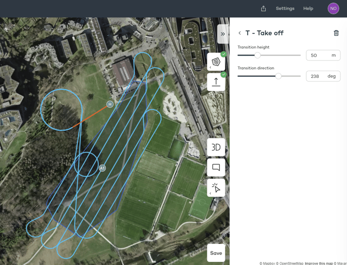
Take off parameters
- Transition height: height above home that the drone transitions into forward flight.
- Transition direction: the direction of the loiter circle that the drone will use to loiter up to the flight height.
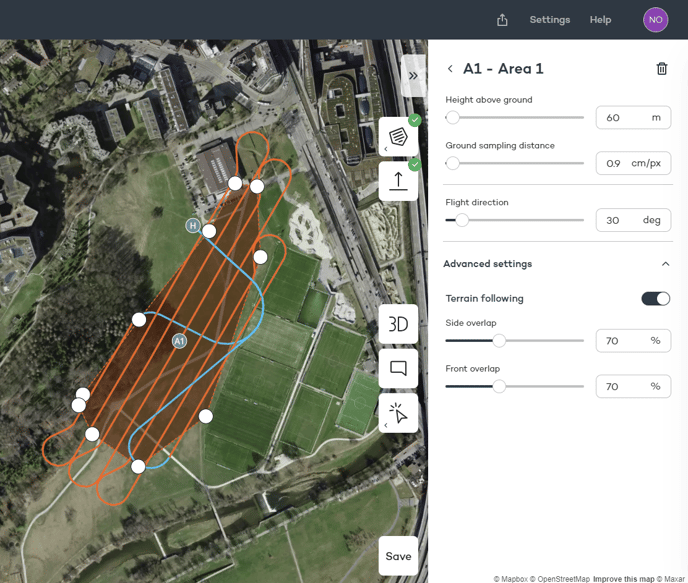
Area parameters
- Height above ground: flight above ground that the drone will use to map the area
- Ground sampling distance (GSD): size of a pixel on the ground. It is directly linked to the flight height, which you can adjust alternatively
- Flight direction: direction of the sweeps
- Advanced settings: Enable or disable terrain following for this flight and set the side and front overlap. Terrain following is enabled by default.
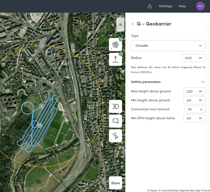
Geobarrier and safety parameters
Select the type of geobarrier among circular and polygonal. The default option is the circular geobarrier, which is a circle centered around the home point.
Learn more about how to define correctly the safety parameters for your flight plan in the article Safety Parameters.
Flight plan safety and quality assessment
The safety of the flight plan, especially in challenging terrain, can be assessed using tools such as the 3D flight plan, the altitude graph, and the colorization of the flight lines according to the GSD or the height above the ground.
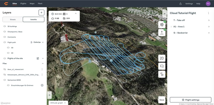
3D view
Click on the 3D button to enable the 3D view of the terrain and the flight plan. Zoom in on the different parts of the flight plan and ensure that the flight lines are at a safe distance from objects, like buildings, and the terrain. Follow the flight plan from takeoff to landing and make sure to understand the loiter circles that the drone uses to fly to the first line and return from the last one. Ensure that in steep terrain, the flight lines are parallel to the contour lines.
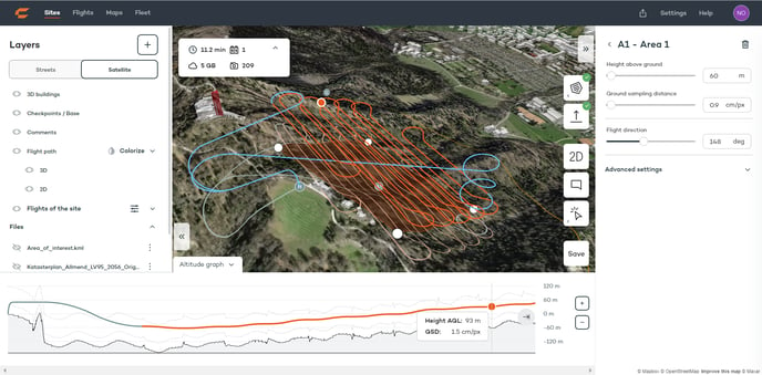
Altitude Graph
The altitude graph is located in the lower part of the screen and can be displayed by clicking on the Altitude graph button at the bottom left corner. Placing the mouse cursor at any point on the altitude graph displays the height above ground for this point and the GSD, as well as the drone's location on the flight path. This can be done in 2D and 3D view. The part of the flight plan that is being modified at any moment appears in orange.
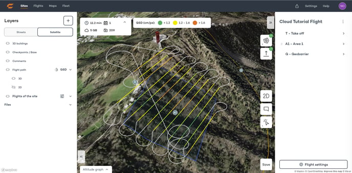
Colorize flight path by GSD
Colorizing by GSD displays the different segments of the flight path with a different color according to the GSD of the images in each segment. The clusters are created based on the defined GSD for the flight. The areas can be viewed where the GSD is yellow or orange, which means that the images will have a higher than specified GSD. The color can be corrected by changing the flight direction or splitting the area into smaller ones.
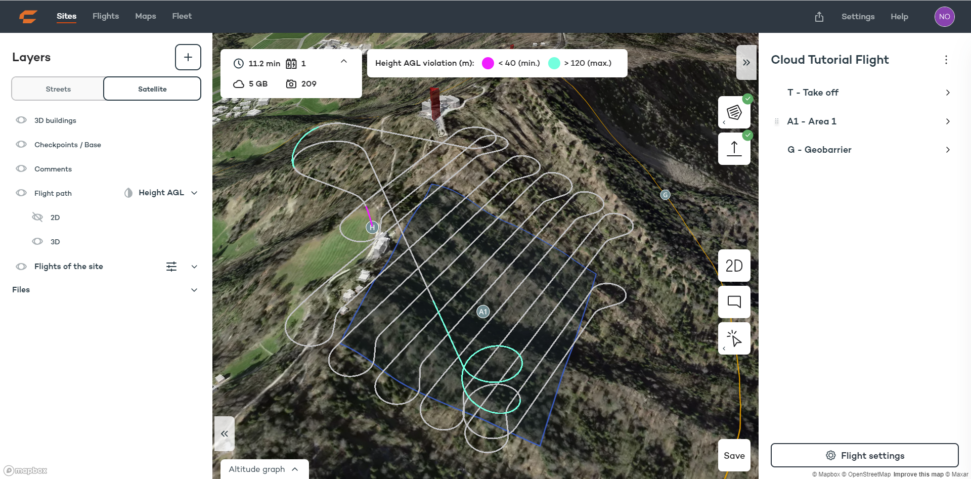
Colorize flight path by height violations (Height AGL)
Colorizing by height AGL displays the different segments of the flight path with a different color according to the distance to the ground. Purple parts indicate where the drone is closer to the ground than the specified minimum height above ground parameter. Pay additional attention to these parts and ensure that there are no objects and that the drone does not approach too much to the ground. Blue areas indicate where the drone exceeds the maximum height above ground parameter.
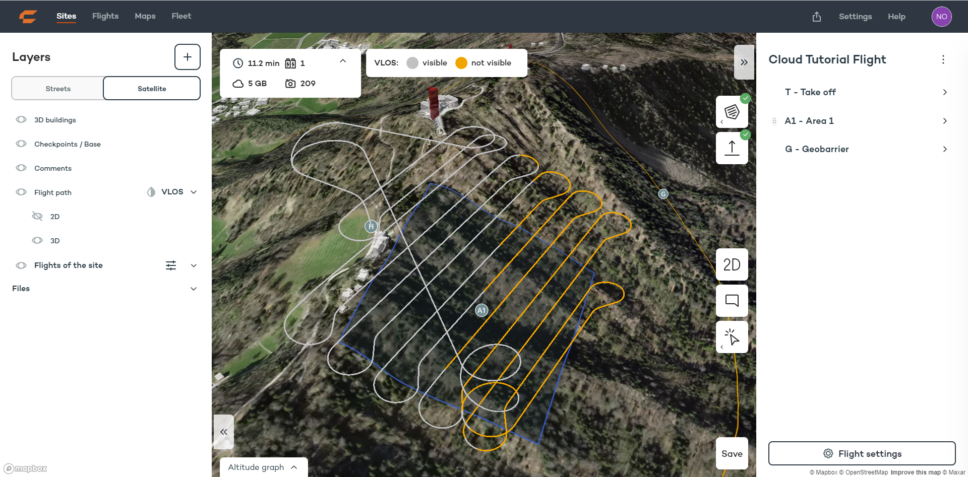
Colorize flight path by VLOS
Colorizing by VLOS displays the parts of the flight which will not be visible from the take-off point based on terrain obstructing the view to the drone. Buildings and vegetation are not taken into account.