The following step-by-step instruction shows how WingtraOne PPK projects can be processed in custom grid coordinates without using ground control points (GCPs). The WingtraOne images are geotagged using WingtraHub then transformed into local coordinates using Trimble Business Center (TBC) before importing into Pix4D.
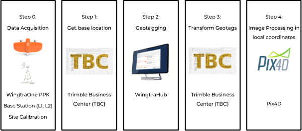
Step 0: Data acquisition in the field
- Site calibration: once you approach the survey site it is important to gather the calibration files (.jxl, .dc, .cal, .job) that contain the "key" parameters to unlocking the conversion from WGS84 to grid coordinates. Our goal is to match our drone PPK data to an existing survey. If there is no existing survey then you will need to create one, and if there is no calibration file you must use ground control in order to process the images.
- Base station logging: set up a GNSS base station (L1 + L2) on one of the known control points of the site calibration and log for the complete flight duration. Convert the receiver file (*.t00, *.t01, *.t02) to a RINEX file using the Trimble software Convert to RINEX.
- WingtraOne PPK data acquisition: fly WingtraOne PPK and get the WingtraPilotProject folder from the camera SD card.
Step 1: get the base location (TBC)
- Open TBC and create a project
- Import the Trimble project file (.jxl, .job, .dc, .cal) that contains the site calibration by drag and drop. If you don't have a calibration file you will need to set up the coordinate system manually.
- Adjust the project settings to display coordinates with high-decimal precision.
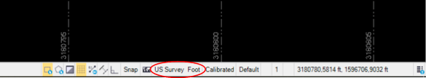
- Open the project settings by clicking on the currently-selected unit on the bottom right (e.g., US Survey Foot)
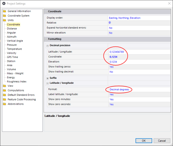
- Select Units, then Coordinate.
- Change the settings so that the coordinates are displayed with enough decimal precision and click OK.
- Select the point on which the base station was placed in the Project Explorer. In the displayed properties, you will find the coordinates in WGS84 (local coordinates)
- Make sure to extend the view in order to see all digits.
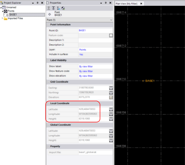
- Convert height to meters if needed.
.png?width=518&name=unnamed%20(25).png)
Step 2: geotagging in WingtraHub
- Open WingtraHub.
- Specify the path to the WingtraPilotProjects folder that contains your flight imagery.
- Select the flight you want to geotag and click Next.
- Select the RINEX files by clicking on Base file(s)
.png?width=600&name=unnamed%20(23).png)
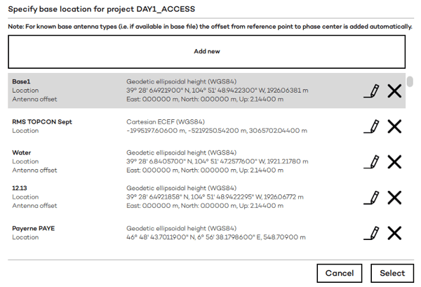
- Add a new base location in WingtraHub by clicking on Base location, then Add new.
.png?width=600&name=unnamed%20(24).png)
- Make sure to specify that the longitude is west. Add a W or minus sign. Specify the antenna offset up: it is equal to the height of the pole up to the bottom of the antenna. If the antenna type is given in the RINEX file, the antenna phase center offset is added automatically. If it is not given, add it to the pole height.
.png?width=600&name=unnamed%20(18).png)
- Select base location.
- Start processing.
.png?width=600&name=pasted%20image%200%20(1).png)
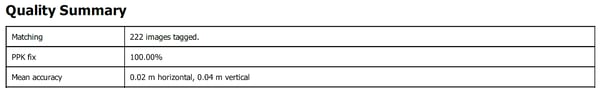
- Once processing is finished, check the output report of WingtraHub. Make sure you have a good PPK fix and accuracy before moving on.
Step 3: Transform geotags to local coordinates (TBC)
- In TBC, click on import in the home view, top left.
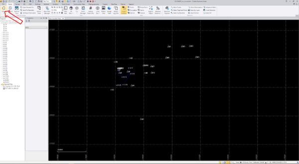
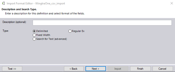
- Open import format editor to define the structure of the .csv.
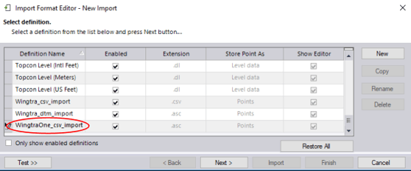
- Create a new definition (in the future the created definition can be selected)
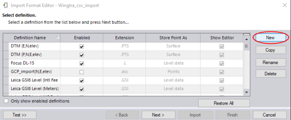
- Give it a meaningful name, e.g., WingtraOne_csv_import.
- Click on Next (2 times)
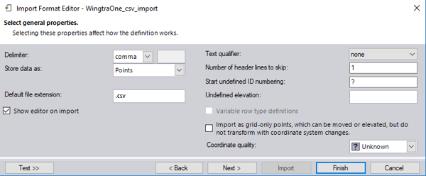
- Specify the parameters as displayed below, and click on Next.
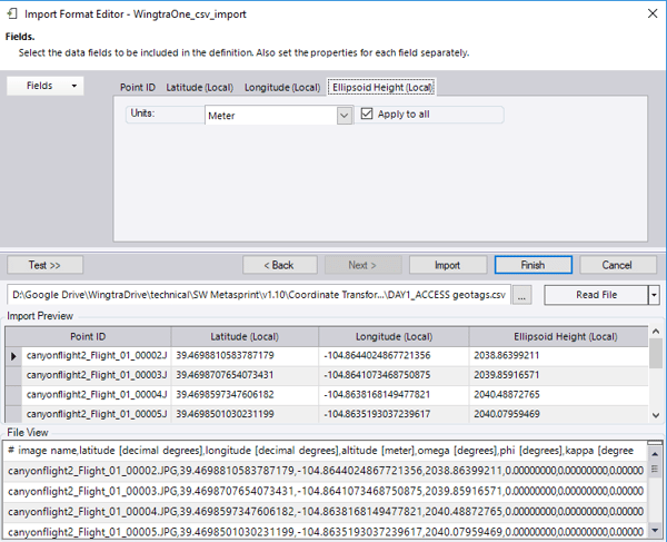
- Add fields by clicking on Fields and selecting point ID, latitude (local), longitude (local), ellipsoidal height (local). Make sure the unit for angles is in decimal degrees, and for the ellipsoidal height select Meter.
- Select the .csv with the geotags in the OUTPUT folder in the WingtraPilotProject folder.
- Check out the import preview and click on Import.
- Check out the location of the image geotags relative to the site calibration points to ensure the coordinates were imported correctly.
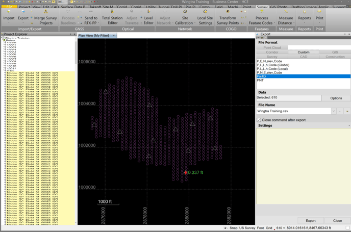
- Open the Export window.
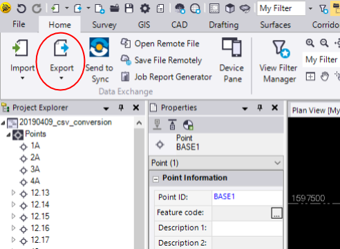
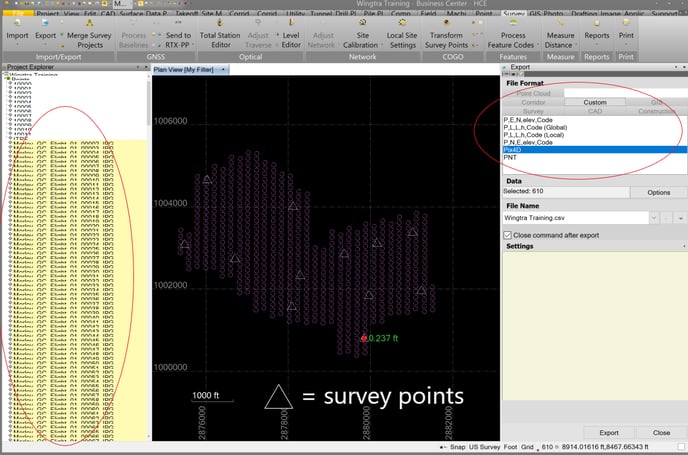
- Select all geotag points in the project explorer on the left.
- In the Export window on the right, select Custom (P, E, N, elev, Code).
- Under File Name, specify the name of the output file and its location.
- Click on Export to save the coordinates to a .csv file.
Step 4: Image processing in local coordinate system “Arbitrary” (Pix4D)
- Open Pix4D.
- Create a new Pix4D project.
- Import the WingtraOne images. (If you get a warning that more than 80% of the image coordinates are the same, click OK).
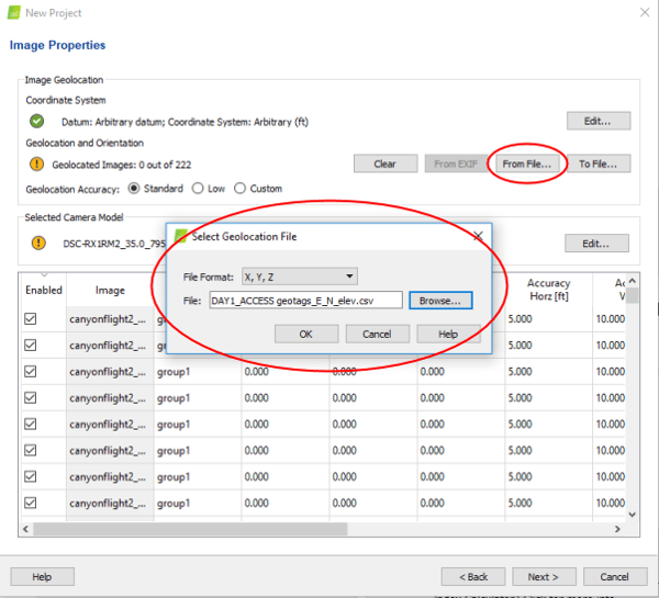
- Change the image coordinate system to arbitrary and choose the unit corresponding to your local grid coordinate system (ft or m).
-1.png?width=600&name=unnamed%20(9)-1.png)
- Import geolocation from file… and select the converted .csv.
- Look up the mean accuracy in the WingtraHub processing report.
- Convert it to ft.
.png?width=600&name=unnamed%20(8).png)
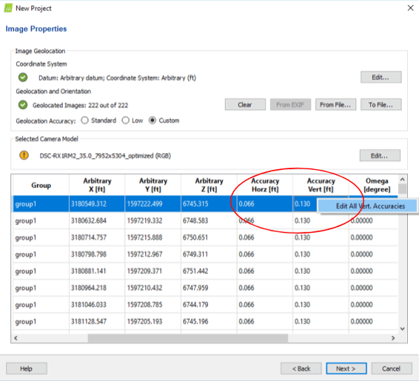
- Change the geotagging accuracy to the mean accuracy derived from the WingtraHub report. Double right-click the Accuracy columns to edit all rows at once.
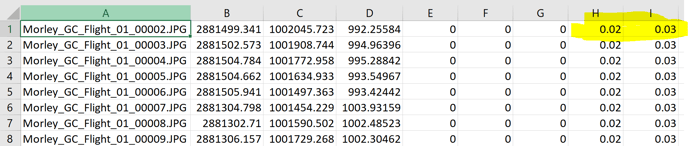
- An alternative to using the mean is to copy and paste the original OUTPUT CSV file column headers for accuracy. Just make sure to convert to feet.
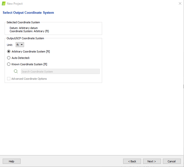
- Select the output coordinate system, which is the same as the input coordinate system (arbitrary and ft).
- Select your desired processing options template.
- Run only 1. initial processing (unselect step 2 and 3).
Step 5: verify your data in local coordinates (optional)
- Once the first step is processed, import checkpoints:
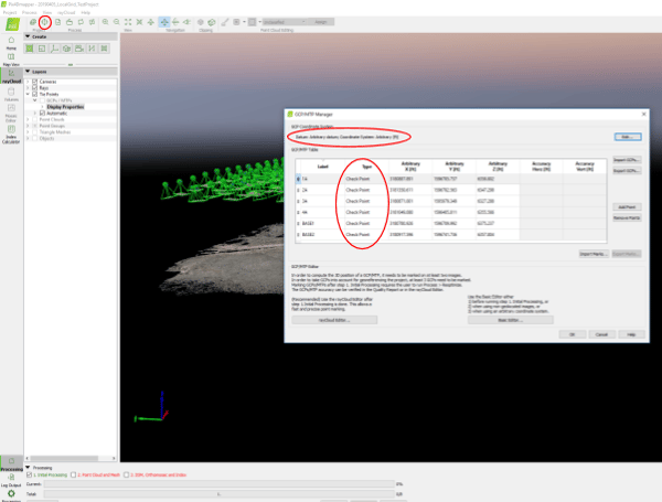
- Open the GCP/MTP Manager (second icon top left).
- Make sure the selected coordinate system is arbitrary.
- Change the type of the points to checkpoint by double-clicking in the field.
- Mark the checkpoints in the images:
- Select a checkpoint in the ray cloud editor list on the left.
- Move the mouse over a preview image on the right and press space.
- Click on the center of the checkpoint and press space again.
- Mark every checkpoint in approximately eight images.
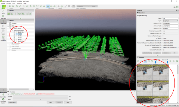
-1.png?width=600&name=unnamed%20(2)-1.png)
- Re-optimize the project by clicking on Process, then Re-optimize
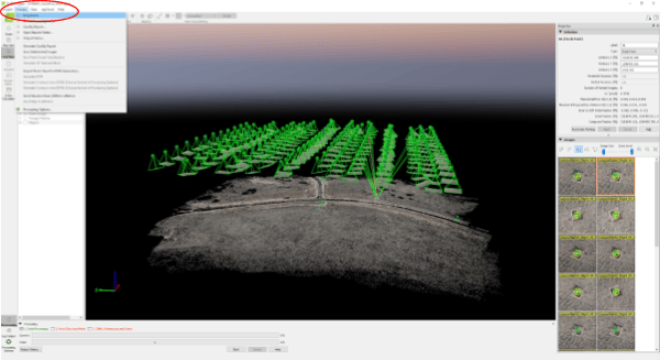
- Generate a quality report.
.png?width=543&name=pasted%20image%200%20(4).png)
- Assess the accuracy by checking out the checkpoint errors in the quality report.
- If you are using a base station within the survey area, you can expect a RMS error for X and Y equal to 1 x GSD, and for Z it will be 2-3 x GSD.
.png?width=477&name=unnamed%20(27).png)
- Now you can run step 2 and 3. If needed, change the processing options to select your desired outputs.
- The outputs are in your local grid coordinate system and can be combined with your existing data in TBC or any other third party software.