The following step-by-step instruction shows how WingtraOne PPK projects can be processed and transformed to your custom grid coordinates in Pix4D using ground control points. WingtraOne images are geotagged using WingtraHub. The workflow is tailored to work with any survey software that creates the site calibration.

Step 0: data acquisition in the field
- Site calibration: measure several points in your area of interest with a GPS rover. Based on these points, run a site calibration. Now you have a project file that contains the coordinates of all points and its conversion from WGS84 to grid coordinates.
- Place aerial targets on a minimum of three points that are part of the site calibration. Or mark them so that they are visible on aerial images.
- Base station logging: set up a GNSS base station (L1 + L2) on one of the calibrated points and log for the complete flight duration. Convert to RINEX format if necessary.
- WingtraOne PPK data acquisition: fly WingtraOne PPK and get the WingtraOneProjects folder from the camera SD card.
Step 1: geotagging in WingtraHub
- Open WingtraHub.
- Specify the path to the WingtraPilotProjects folder.
- Select the flight you want to geotag and click Next.
- Select the RINEX files by clicking on Base file(s).
- You do not need to specify a base location, because the project will be accurately geo-referenced using GCPs. WingtraHub will take the first measurement within the RINEX file as base location. The approximate position is good enough for geotagging.
- Start processing.
- When processing is finished, check the output report of WingtraHub. Make sure you have a good PPK fix and accuracy before moving on.
.png?width=688&name=unnamed%20(17).png)
Step 2: initial image processing in Pix4D
- Open Pix4D.
- Create a new Pix4D project.
- Import the WingtraOne images. (If you get a warning that more than 80% of the image coordinates are the same, click OK.)
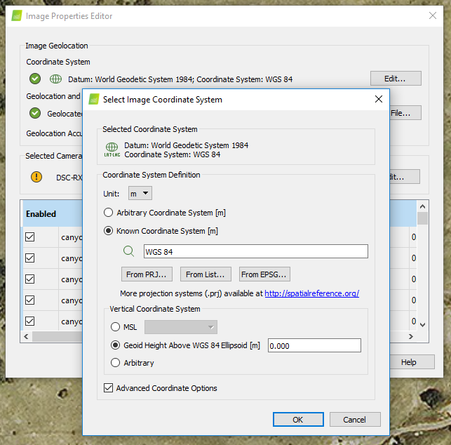
- Change the image coordinate system to WGS84 and Geoid Height Above WGS84 Ellipsoid [m] by enabling Advanced Coordinate Options.
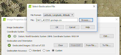
- Import geolocation from file … and select the .csv file created by WingtraHub (WingtraPilotProjects > Flight name > OUTPUT).
- Leave the output coordinate system as it is. We will change it later.
- Select your desired processing options template.
- Run only 1. Initial processing (unselect step 2 and 3).
Step 3: use GCPs to project into local grid coordinates
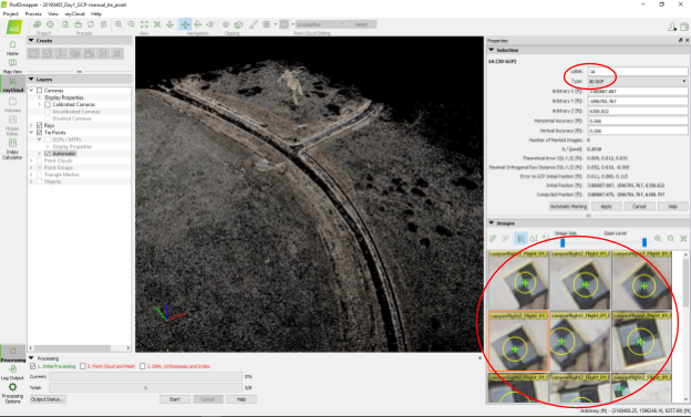
- Mark manual tie points:
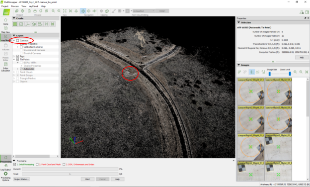
- Go to the ray cloud view.
- Disable the cameras.
- Localize your GCPs and click Next to GCP in the point cloud.
- To simplify this step, mark the GCP locations on a map when you are placing them in the field. Number the targets or color them differently to easily identify them.
- Click on “New Tie Point.”
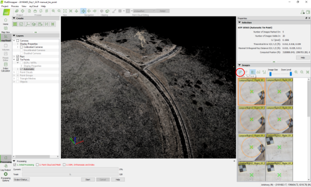
- Name your new tie point after your GCP (top right).
- Select the Type 3D GCP.
- Move the mouse over a preview image on the right and press the space bar.
- Click in the center of the GCP and press space again.
- Mark every GCP in approximately eight images.
-1.png?width=688&name=unnamed%20(2)-1.png)
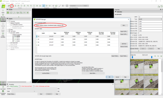
- Open the GCP/MTP Manager (second icon, top left).
- Select the GCP coordinate system:
- Choose desired unit (e.g. feet).
- Select Arbitrary Coordinate System.
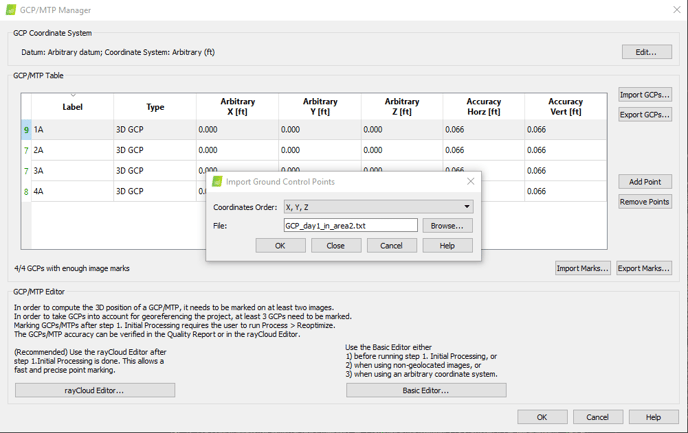
- Import the GCP coordinates by clicking on Import GCPs.
- Select the .csv containing the GCPs in your local grid coordinates (E, N, elevation).
- Click OK.
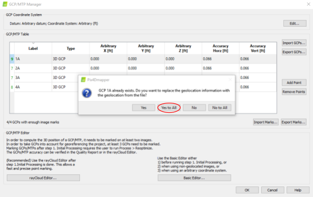
- Pix4D will warn you that the GCPs already exists. Click Yes to All to overwrite the existing GCPs.
- Specify the accuracy of your GCPs depending on your measurement method and if you processed the images using a base location (e.g., 0.1ft horizontal, 0.3ft vertical). If you do not have enough GCPs or a good balance, it could hurt the accuracy of the model. In that case, it is suggested to set the accuracies lower than the default and rely more on the images.
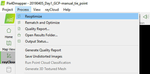
- Re-optimize the project by clicking on Process, then Re-optimize.
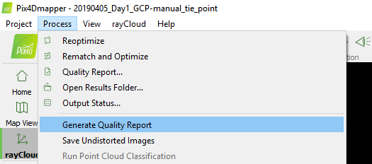
- Generate Quality Report.
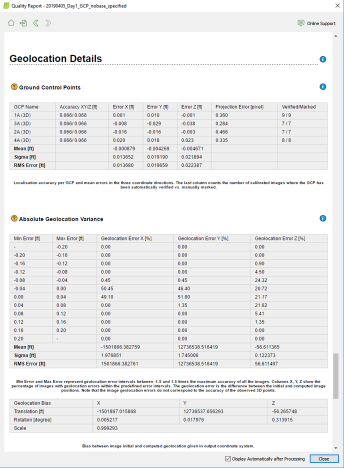
- Assess the accuracy by checking out the GCP errors in the quality report
- If you are using a base station within the survey area, you can expect a RMS Error for X and Y equal to 1 x GSD, and for Z between 2-3 x GSD.
- Now you can run step 2 and 3. If needed, change the processing options to select your desired outputs.
- The outputs are in your local grid coordinate system and can be combined with your existing data in TBC or any other third-party software.