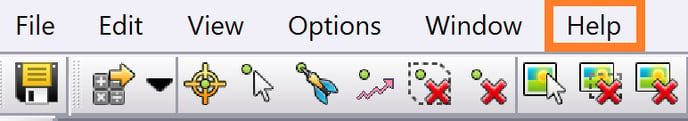
This guide is not intended to be a full guide on how to use UAS-Master and is tailored to processing only Wingtra data. For further help with UAS-Master click on the Help tab to get access to the manual and links to the video tutorials.
Control Points Project Setup
Depending on how you captured the ground control points the initial setup can be different, but Setup 1 is the most preferred.
Setup 1 - If you have a survey project established it is best to begin in TBC by loading in the .JOB or .DC file which holds the coordinate system settings and then import the survey ground points.
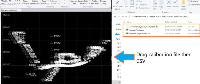
Find or filter the ground targets that will be used for the photogrammetry processing and accuracy verification. Select the control points then click Send to UASMaster and it will export the local control points into UAS-Master.
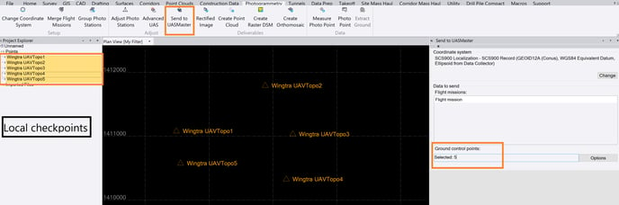
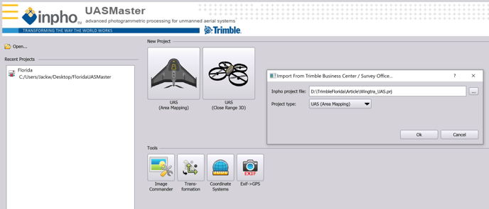
UAS-Master will then prompt to name the project and specify a folder location.
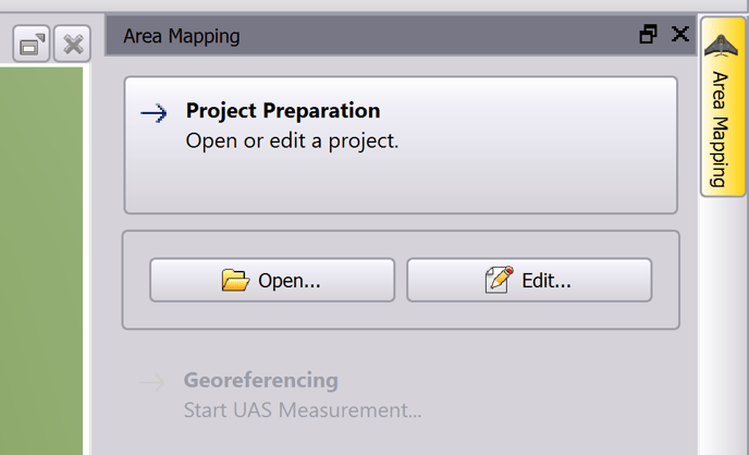
Next click Edit to open the Project Editor.
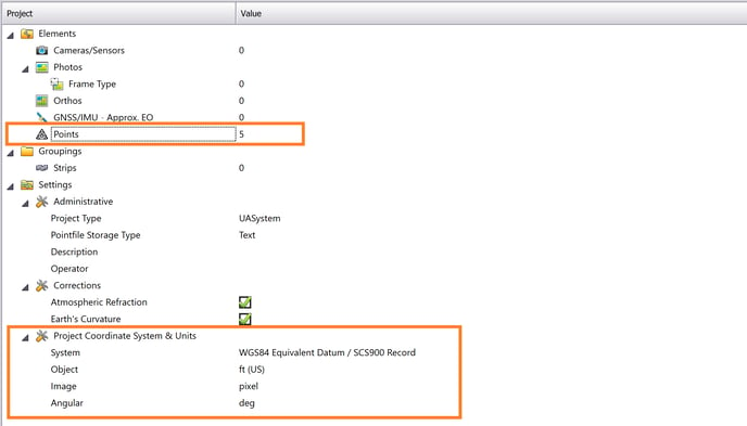
The points are now loaded in the project.
 Skip to the next section after this step.
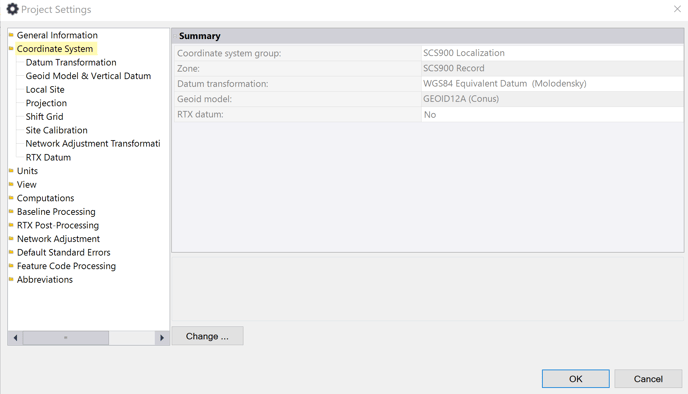
Setup 2 - If there are no project calibration files then configure the project settings manually by opening the Project Settings dialog. Then follow the same export to UAS-Master process in Setup 1.
Setup 3 - The GCPs can be set up in UAS-Master instead of first importing into TBC. On the import of the points, specify the column order, units, and coordinate system.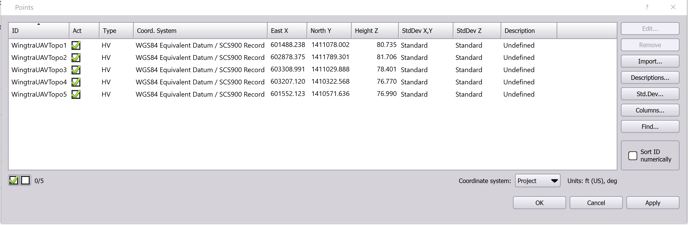
Image and GNSS Import
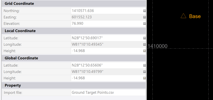
Dragging the local base station file into TBC with the project setup will display the WGS84 equivalent position in order to obtain the base location to enter into Wingtrahub. Find the base point to view the properties and paste the global coordinates into WingtraHub.
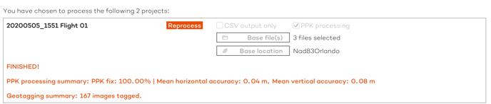
When post-processing the images in WingraHub it is easiest to uncheck CSV output only so that the geolocation information is stored in the metadata of the image.
Once the photos are geotagged the next step is to import the images by clicking on Photos in the Project Editor. It will prompt you to find the folder then click Next.
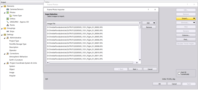
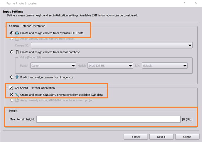
Click Next again until reaching the following screen which is an important step to instruct the software on where to read the geolocation from. The camera should be set up using the EXIF data. The GNSS/IMU information should be assigned also from the EXIF data unless the CSV only was exported from WingtraHub, but it's suggested to write the EXIF onto the images. Using the ground control point elevations, enter the mean terrain height.
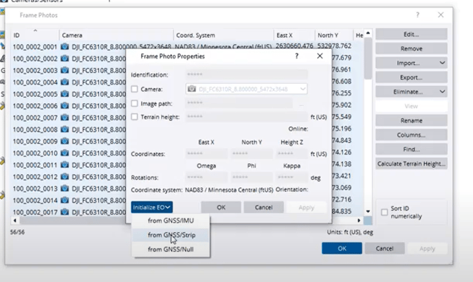
For CSV import method only - You will need to uncheck GNSS/IMU- EO then import the CSV through the GNSS/IMU - Approx. EO tab. On version 10 once you have imported the GCPs and generated the strips you will need to go back into the Frame Photos tab, Select All, and then Edit. In the Properties window, switch from GNSS/Null to GNSS/Strip. There are variations with SW versions so if you struggle with the project setup don't use the CSV method.
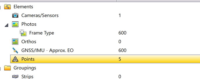
The values should now be filled in for the Cameras/Sensors, Frame Type, GNSS/IMU - Approx. EO, and Points.
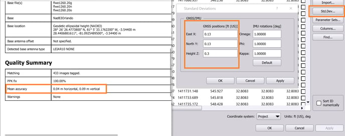
Double click on the GNSS/IMU - Approx. EO element to specify the accuracy of the image locations. On the right side click on Std.Dev... then enter the accuracies from the Wingtrahub processing report. Remember to convert units if applicable.
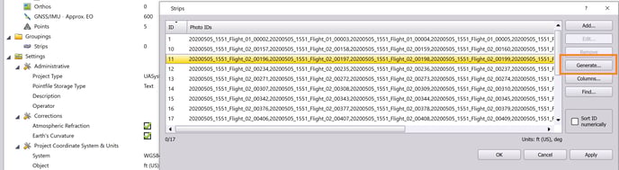
The last thing to do in the Project Editor is to generate Strips then save the project.
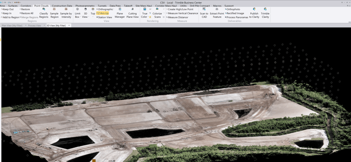
We can close the Project Editor now to view the home screen. You should see the image positions overlayed on top of the ground control points.
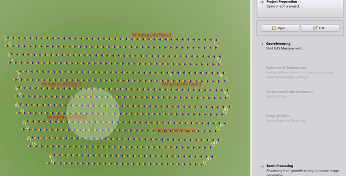
Click on Georeferencing to begin the next section.
Georeferencing
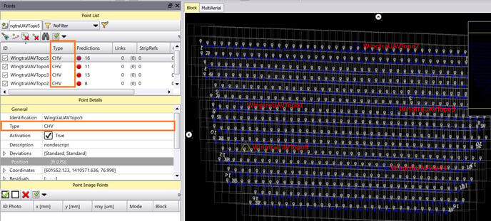
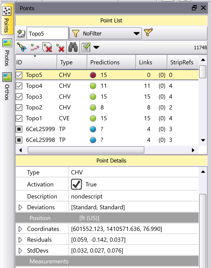
After the georeferencing window opens it will look like the following screenshot. The first thing to do is edit the survey point type to CHV which means checkpoint XYZ. This is where to change the ground control points into checkpoints or vice versa.
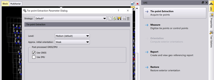
The marking of the checkpoints doesn't happen until after generating a sparse point cloud. Click Tie-point Extraction to bring up the dialog and make sure Use GNSS is checked to tell the SW the images are PPK referenced. Then hit start.
The yellow triangle after the tie point extraction will not be precisely over the targets until after we run the orientation and calibration step.
After the sparse point cloud is produced mark the checkpoints to verify the accuracy before creating the surface/ortho. Using 1 point as a GCP will help tighten up the project, and then mark the rest of the checkpoints will help adjust the block by being manual tie points.
The Yellow triangle is the estimated position. The white triangle is the calculated position. The best matching strategy for marking GCPs is to Refine and Compliment. The blue X which is your selection should be in the middle of the target along with the white triangle. Measure the checkpoints by marking the center of the targets until they are all green.
Save the project.
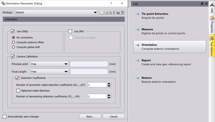
Run the bundle block adjustment by selecting the Orientation tab. Match the settings below then click start. The yellow calculated triangles should now align accurately over the target. If they are not close enough use 1 or 2 GCPs to tighten it up. You will need to run the orientation process again after making changes.
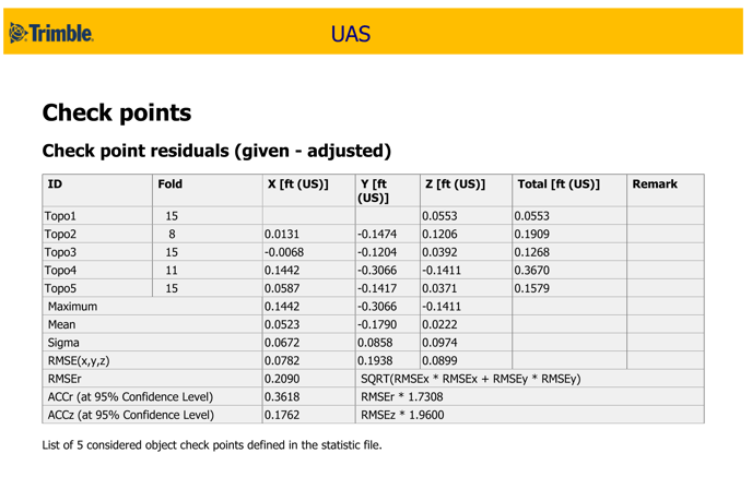
The next tabular step is to generate and view the report. Scroll down to see the checkpoint accuracies. If they are within tolerance proceed to the next step in creating a surface. If the accuracies are not good consider switching checkpoints to GCPs, review transformations, image exposure, truncations, base station accuracies, overlap, and tie point strength. You may need to unselect Camera Calibration for running the Orientation step a 2nd time, and Compute global shift if there are reference system issues.
Generate the surface and ortho to the desired density and resolution.
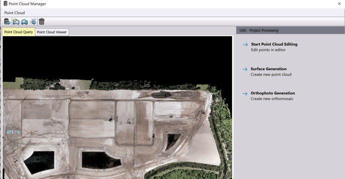
After the processing is complete under the project tab there is a command to send the outputs to the TBC project.
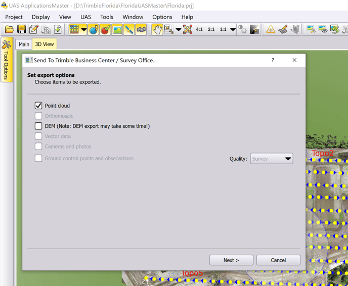
The survey points, checkpoints, aerial points, and point cloud can now be viewable in unison for further analysis and use.